Direct Drive Technology: “Battle Proven” Performance in a Process Gauge
The military has used direct drive gauges on aircrafts, tanks and submarines since the 1960s for one simple reason: they are extremely resistant to shock, vibration and pulsation. Direct drive gauges have been known to survive direct missile strikes when placed within the hulls of battleships during military testing. Over time, direct drive gauges have proven themselves in numerous mission critical applications like jet fighter struts, tank gun turrets and submarine ballast tanks. Imagine having this same “battle proven” performance in a process gauge for your mission critical applications!
At the technological heart of the WIKA Direct Drive process gauge is our exclusive Bourdon tube made of Inconel® X-750 alloy. Compatible with most media types, this super-alloy is highly resistant to temperature extremes and has excellent oxidation and corrosion properties. Every WIKA Bourdon tube is meticulously handmade and then stress relieved in our proprietary heat treatment chambers. To provide superior strength and performance in the most aggressive environments and temperature extremes, all wetted parts on the WIKA Direct Drive process gauge are nickel-brazed.
Features

- Medical-grade pointer shaft that rotates on a jeweled sapphire bearing that eliminates pointer friction
- External adjustment screw to re-zero the pointer n Porous filter to protect the pressure inlet from clogging
- Thermoplastic case for extreme temperatures
- Shatterproof polycarbonate window
- 150% overpressure protection without any loss of calibration
- Solid-front, blow out back safety case design to meet industry safety requirements
WIKA Direct Drive gauges are manufactured in the United States and come with a full 6-year warranty that beats the competitors’ warranties 6 to 1.
Technical Specifications Overview
Wika Direct Drive Process Gauge: Model 232.34DD
The WIKA Direct Drive process gauge comes with a process industry standard ASME B40.100 Grade 2A (+/-0.5% of span) accuracy; a silicone dampened Bourdon tube to eliminate pointer flutter in severe vibration and pulsation applications; an adjustable process gauge pointer for recalibration; and a yellow case to signify to workers that this gauge is used for the tough applications.
Wika Model 232.34DD Datasheet
Wika Direct Drive Test Gauge: Model 332.34DD
The WIKA Direct Drive test gauge has a calibration industry standard ASME B40.100 Grade 3A (+/-0.25% of span) accuracy; a knife-edge adjustable pointer for precise pressure readings; a mirror band dial to remove reading error; a calibration certificate traceable to the National Institute of Standards and Technology (NIST); and standard black case.
Wika Model 332.34DD Datasheet
Advantages of the WIKA Direct Drive gauge over conventional gauges include:
- Very long service life
n Excellent for problem applications that contain shock, vibration or pulsation
- Contains only one moving part
- No gears, linkages or springs to wear or break
- No loss of accuracy
- No recalibration required
WIKA Direct Drive gauges are great solutions for these problem applications:
- Environments that contain continual shock and vibration
- Processes that have problems with pressure surges and spikes
- Pressure systems that have high cyclic rates
- Installations with temperature extremes
If you would like
additional information about WIKA Direct Drive Process Gauges, Wika Direct Drive Test Gauges or
other WIKA
Products
please contact Forberg Scientific, Inc.
Toll Free: 855-288-5330Email: mechanicalsales@forberg.com
Intelligent control heads enable complete decentral automation of hygienic production processes, by Chris Hoey
In the food and beverage industry, and also in the production of medicines and cosmetics, excellent hygiene in processes and around the plant plays a key role. This is ensured by stringent legislative regulations. Standards such as HACCP (Hazard Analysis and Critical Control Points) for food processing and GMP (Good Manufacturing Practise) for FDA-compliant processes in the pharmaceutical industry define extremely stringent requirements for cleanliness, safety and product quality. In addition, legislation requires that all processes must be constantly monitored and documented in these areas. In an increasingly competitive global environment, companies of this industry are at the same time forced to make their production processes as efficient and cost-effective as possible, in addition to optimising processes. As a consequence, there is an ever increasing demand for automation at all process and auxiliary circuit levels.
 Pneumatically actuated process and control valves play a key role in the manufacture of foods and beverages, in milk processing and in the pharmaceutical and cosmetic industries. They are the core element of practically every production plant, where they perform numerous different tasks. However, the economical and hygienic aspects of these process fittings in a centrally controlled automation process are not unproblematic. Classical control systems using switch cabinets with valve terminals, I/O system and field bus interface involve considerable expense especially in complex facilities. With this technology, the fittings at the field level are connected to the control units in the switch cabinets through a large number of long control air lines and discrete feedback connections. Apart from planning and installation requirements for such solutions, they are not entirely optimal as regards hygiene. According to HACCP, every additional control air and feedback line within the production plant is a potential source of contamination and other risks and must therefore be monitored, serviced, cleaned and documented regularly, which is a costly undertaking.
In shop floor practice the control air lines can be quite long, which increases air consumption and has a negative effect on the switching times of the fittings. The situation is worsened even more by the high power requirement - e.g. for evacuation of air from chambers and hoses - which is undesirable in terms of energy efficiency. The fact that the pilot valve operating level is at a distance from the fitting makes it even more difficult to commission, maintain and extend the plant. This also applies to the monitoring of processes.
Intelligent valve systems make switch cabinets superfluous
A viable alternative to the use of central switch cabinets is the integration of the required automation functions in the fittings themselves. In this case, the process control system is only in charge of control and status monitoring. At field level, pneumatically operated valves are used. These can be equipped with all required automation components such as pilot valves with manual actuation, electrical feedback units and optical status indicators, field bus interfaces and even positioners and process controllers. By integrating an AS interface as a field bus interface, the entire range of advantages of this approach can be fully utilised. All that is required for power supply, feedback and communication is a two-wire line connecting the PLC with up to 62 valves. Each process valve is individually connected to the main compressed air supply line installed in the field, whereby these connections are kept as short as possible. This minimises the number and length of hose and wire connections.
Pneumatically actuated process and control valves play a key role in the manufacture of foods and beverages, in milk processing and in the pharmaceutical and cosmetic industries. They are the core element of practically every production plant, where they perform numerous different tasks. However, the economical and hygienic aspects of these process fittings in a centrally controlled automation process are not unproblematic. Classical control systems using switch cabinets with valve terminals, I/O system and field bus interface involve considerable expense especially in complex facilities. With this technology, the fittings at the field level are connected to the control units in the switch cabinets through a large number of long control air lines and discrete feedback connections. Apart from planning and installation requirements for such solutions, they are not entirely optimal as regards hygiene. According to HACCP, every additional control air and feedback line within the production plant is a potential source of contamination and other risks and must therefore be monitored, serviced, cleaned and documented regularly, which is a costly undertaking.
In shop floor practice the control air lines can be quite long, which increases air consumption and has a negative effect on the switching times of the fittings. The situation is worsened even more by the high power requirement - e.g. for evacuation of air from chambers and hoses - which is undesirable in terms of energy efficiency. The fact that the pilot valve operating level is at a distance from the fitting makes it even more difficult to commission, maintain and extend the plant. This also applies to the monitoring of processes.
Intelligent valve systems make switch cabinets superfluous
A viable alternative to the use of central switch cabinets is the integration of the required automation functions in the fittings themselves. In this case, the process control system is only in charge of control and status monitoring. At field level, pneumatically operated valves are used. These can be equipped with all required automation components such as pilot valves with manual actuation, electrical feedback units and optical status indicators, field bus interfaces and even positioners and process controllers. By integrating an AS interface as a field bus interface, the entire range of advantages of this approach can be fully utilised. All that is required for power supply, feedback and communication is a two-wire line connecting the PLC with up to 62 valves. Each process valve is individually connected to the main compressed air supply line installed in the field, whereby these connections are kept as short as possible. This minimises the number and length of hose and wire connections.

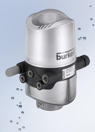
For auxiliary circuits such as steam, compressed air or cleaning media, the valve specialist Bürkert offers fluid control systems with the intelligent valve systems of the ELEMENT series for creating decentralised automation solutions. The latest addition to this solution portfolio is the new control head Type 8681, which was designed especially for use with pneumatically actuated hygienic media valves. The features of a decentralised automation solution in hygienic production processes can be used to good advantage not only in the auxiliary circuits, but throughout the plant at all process levels. In the planning of new plants, the use of conventional switch cabinets can be eliminated consistently. Existing plants can be converted from central to decentralised automation step-by-step, using the existing media valves.
New universal control head for hygienic process fittings
The Type 8681 control head is universally adaptable by means of adapters and can be combined with all commercially available valve types, such as flap valves, ball valves and single and double-seat valves, regardless of the manufacturer. Within the framework of a decentralised automation concept the control head, as a central unit for the hygienic process valves, performs all pneumatic actuation, feedback and diagnostic functions, as well as bus communication. Depending on the process valve, as many as three pneumatic driver chambers can be controlled separately.
The switching positions of the hygienic process valve are measured by the control head via an inductive analogue distance sensor for monitoring strokes of up to 85 mm and then transmitted to a master controller. After installation of the control head on the valve actuator the switching positions are automatically determined by a fast and reliable teach-in function, which eliminates the need for time-consuming manual configuration. If a fourth switching position is required, it can be read in by an externally mounted inductive proximity switch.

For optimal adaptation to the respective valve and process, the switching speed of each driver chamber can be set individually for both directions of movement by means of a restrictor function integrated in the pilot valve. In addition, a non-return valve prevents faulty switching of other driver chambers of the process valves due to back pressure. Independent of the power supply, each pilot valve can additionally be switched manually by means of a mechanical control. Thanks to a patented magnetically coded manual control, it is possible to switch the main actuator for maintenance purposes from outside even in the case of a completely enclosed device - ensuring full IP protection at all times.
 A highly visible three-colour optical status display with high-power LEDs, which is integrated in the control head, provides for an optimum overview at the field level. In addition to electrical feedback to the master controller, it also signals the current switching position of the process valve, facilitating diagnosis and maintenance within the system itself. Diagnostic functions such as required maintenance or errors are likewise signalled visually and can be read out in detail via a service interface. This communication can be wireless via a Bluetooth module or via the integrated USB interface.
Hygienic control valves are also suitable for decentralised automation
The use of one of the positioners or process controllers of the ELEMENT series allows the decentralised automation of control valves, in addition to the process valves. The ELEMENT process controllers are optimised for cleaning and use in the wet areas of hygienic processing plants; their outer geometry, materials, surface quality and sealing properties comply with EHEDG guidelines. The compact positioners are installed directly on the pneumatic actuator to save space and require no external hoses, thanks to the internal control air supply. Installation and commissioning are facilitated by the use of intelligent positioners with automatic adaptation and process controllers with automatic control circuit detection and parameter optimisation. Communication is achieved via Profibus DPV1, Device NET or the AS-Interface.
One decentralised system solution for all process levels
With the addition of the new Type 8681 control head to the ELEMENT series, Bürkert now offers a complete product portfolio for decentralised process automation in food and beverage production, breweries and the milk processing and pharmaceutical industries. The range of products extends from the process valve with an integrated pilot valve, as well as electrical and simple optical feedback all the way to the decentralised control of aseptic, hygienic control valves by means of a control head and process controller in complex production plants. decentralised automation can therefore be used in all processes for entire plants and installations, enabling users from these industries to combine the requirements for hygiene and safety with a high degree of automation and efficiency. Since the new control head can be used with virtually all available fittings regardless of the manufacturer, there are practically no limits to decentralised automation with uniform standards.
To download the Burkert ELEMENT Conrtrol Valves
datasheet: click here
The new flow transmitters at a
glance
A highly visible three-colour optical status display with high-power LEDs, which is integrated in the control head, provides for an optimum overview at the field level. In addition to electrical feedback to the master controller, it also signals the current switching position of the process valve, facilitating diagnosis and maintenance within the system itself. Diagnostic functions such as required maintenance or errors are likewise signalled visually and can be read out in detail via a service interface. This communication can be wireless via a Bluetooth module or via the integrated USB interface.
Hygienic control valves are also suitable for decentralised automation
The use of one of the positioners or process controllers of the ELEMENT series allows the decentralised automation of control valves, in addition to the process valves. The ELEMENT process controllers are optimised for cleaning and use in the wet areas of hygienic processing plants; their outer geometry, materials, surface quality and sealing properties comply with EHEDG guidelines. The compact positioners are installed directly on the pneumatic actuator to save space and require no external hoses, thanks to the internal control air supply. Installation and commissioning are facilitated by the use of intelligent positioners with automatic adaptation and process controllers with automatic control circuit detection and parameter optimisation. Communication is achieved via Profibus DPV1, Device NET or the AS-Interface.
One decentralised system solution for all process levels
With the addition of the new Type 8681 control head to the ELEMENT series, Bürkert now offers a complete product portfolio for decentralised process automation in food and beverage production, breweries and the milk processing and pharmaceutical industries. The range of products extends from the process valve with an integrated pilot valve, as well as electrical and simple optical feedback all the way to the decentralised control of aseptic, hygienic control valves by means of a control head and process controller in complex production plants. decentralised automation can therefore be used in all processes for entire plants and installations, enabling users from these industries to combine the requirements for hygiene and safety with a high degree of automation and efficiency. Since the new control head can be used with virtually all available fittings regardless of the manufacturer, there are practically no limits to decentralised automation with uniform standards.
To download the Burkert ELEMENT Conrtrol Valves
datasheet: click here
The new flow transmitters at a
glance
- Beautiful stainless steel housing in standardized ELEMENT
design
- Long durability and outstanding availability
- Removable, programmable display with backlight
- Programming via joystick
- New processors and software
- Future-proof system architecture
- Protection class IP 65/67
- Resistant to cleaning chemicals
- Up to two 700 mA transistor outputs
- Analog outputs 4-20mA
- UL
approved
To
receive more information on Burkert Element Valves please contact Forberg Scientfic customer service:
Phone: 855-288-5330Email: mechanicalsales@forberg.com
Selection Guidelines
When selecting a diaphragm seal assembly, the following details must be taken into consideration to ensure a safe
and satisfactory operation. For specific technical assistance regarding temperature effects, volumetric compatibility, etc.,
contact the Forberg Scientific customer service department or send a completed diaphragm seal specification sheet to the factory
for analysis.
- Process Composition
- Temperature
- Pressure Range
- Pressure Instrument
- Process Connection
- System Fill Fluid
- Mounting Positions
- Response Time
- Seal and Gauge Matches
1. Process composition
Since the diaphragm and lower housing of the diaphragm seal will be exposed to the process medium, it is critical to
select materials for these components which will be compatible with this medium. Tables are available to assist in the
selection of these materials (see Pressure Gauge Section); however, the customer is the ultimate source for specifying suitable
materials. WIKA cannot guarantee suitability. For information, see numerous reference guides such as corrosion table
reference books. If the pressure fluid is very thick, solidifies, or is full of solids, this should also be taken into consideration.
2. Temperature
Each diaphragm seal measurement system (diaphragm seal, pressure instrument, and cooling element or capillary, if
applicable) is filled with an amount of fill fluid at an ambient temperature of about 70oF. This temperature is referred to as
the system fill temperature. The fill fluid will expand or contract according to temperature changes. This in turn causes
the pressure in the sensing element to rise or fall, thus adding zero shifting effects to the instrument output. To reduce
this effect, the temperatures of the process and the environment should be specified when selecting a diaphragm seal
system (see Diaphragm Seal Specification Sheet). Special advanced calibration techniques can be used to ensure the
best possible accuracy. At temperatures above 300 F, a cooling element or capillary is suggested to protect the pressure
instrument.
3. Pressure range
The displacement volume on the diaphragm seal required to "drive" each diaphragm seal measurement system
(diaphragm seal, pressure instrument and capillary, if applicable) must be greater than the displacement volume needed
to move the pressure sensing element. Normally, the lower the pressure range, the larger the diaphragm is required to
"drive" the system. Conversely, for higher pressure ranges, smaller diaphragms are sufficient. Pressure transmitters also
follow the general rule of the lower the pressure, the larger the diaphragm required.
4. Pressure instrument
As mentioned above (Item 3 - Pressure range), the diaphragm seal must supply sufficient displacement volume to
enable the pressure instrument to reach full scale. As a general rule, smaller size gauges are better suited to low pressure
applications since less displacement volume is required on the part of the diaphragm seal to drive the pressure instrument.
5. Process connection
The process connection is specified by the customer. Most process connections are threaded, flanged, or clamped;
however, additional connections are available. Teflon® coating and lining is only available in flanged connections, since
tapered NPT threads strip off the Teflon® during installation. However, solid Teflon® threaded connections are available
with NPT threads.
6. System fill fluid
WIKA offers a wide range of system filling fluids allowing temperatures from -130 F to 752 F. Chemical compatibility of the
system fill fluid with the process fluid must be carefully considered in the event of a leak. In food processing applications a
nontoxic fluid should be selected. Special fill fluids are also available for oxidizing media such as oxygen and chlorine.
7. Mounting position
Mounting position is important for diaphragm seal systems which include a capillary. The level difference between the
diaphragm seal and the pressure instrument causes a hydrostatic pressure to act on the sensing element:
a. For gauges mounted above the level of the diaphragm seal, the pointer on the dial
of the gauge will be lower than the zero point.
b. For gauges mounted below the level of the diaphragm seal, the pointer on the dial
of the gauge will be higher than the zero point.
The diaphragm seal system can be calibrated to compensate for the effect caused by the hydrostatic pressure,
if the level difference is known in advance.
8. Response time
Response time, i.e., the time it takes the pressure instrument to indicate 90% of the value of a sudden pressure
variation, is especially important for instrument/diaphragm seal assemblies which include a capillary. Response time
increases significantly in systems with long capillaries. In applications requiring long capillaries, response times can be
reduced by using larger diameter capillary tubing and reducing the viscosity of the system fill fluid. Be advised that
increasing the inner diameter of the capillary increases the temperature influence of the measuring system. Forberg Scientific can consult WIKA if detailed information is needed.
9. Seal and gauge matches
For low ranges, gauge preference is 2XX.54 or 2XX.34 for access to perform calibration adjustments. Gauges with crimp
rings might not be usable due to potential recalibration. The table below shows the common matches between gauge
and diaphragm seal types recommended by the WIKA.
If you would like additional information about
WIKA Diaphragm Seals
or other WIKA Products please
contact Forberg Scientific, Inc.
Toll Free:
855-288-5330
Email: mechanicalsales@forberg.com