Thursday, November 1, 2012

UE One Series Seal Oil Skid Cost Reduction

UE ONE SERIES APPLICATION NOTE
One Series electronic switch reliably protects generator with I Am WorkingTM

UE One Series 2XLPA major electrical infrastructure company designs and manufactures power generation turbines that use natural gas, oil, coal and other fuel 
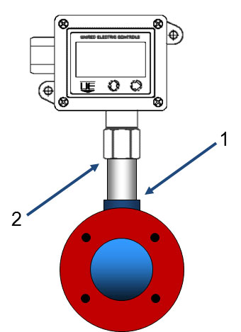
technologies. The company has standardized on One Series model 2XLP43 for measuring gage and differential pressure to replace traditional transmitters, UEmechanical switches and mechanical gauges on their seal oil skids.


THE PROBLEM:
The company needed to lower costs, reduce maintenance and provide more reliable hydrogen-cooled generators for their customers worldwide. In order to monitor pressure remotely, provide switch control and be able to instantly view pressure readings, three discrete instruments were needed – a pressure transmitter, a pressure switch and a local gauge. These three instruments were all connected to the same pressure source using the piping tree arrangement to the right.


Counting all of the tubing, elbows, t-fittings and connections to each instrument and the pressure source, potential leak paths quickly became a problem. Not counting block and bleed valves, there were a minimum of 12 threaded connections where the media could leak. The cost of the stainless steel tubing and fittings, the cost of the labor to plumb and leak-test and the maintenance required should clogging or leaking occur were all considered. Adding in the cost of the instrumentation and considering reliability, clearly a better method was needed.

THE SOLUTION:
The company needed a highly reliable instrument that could evaluate and report its own health status and provide the functions of the three instruments while reducing overall costs. The One Series 2XLP model is primarily a smart pressure transmitter with display that includes a programmable electronic switchswitch + gauge + transmitter all-in-one.

All One Series models include a self-diagnostic feature called I Am WorkingTM that monitors several vital instrument functions and reports health status three ways – locally on the digital display and remotely via the 4-20 mA analog and using discrete switch signals.

The One Series’ I Am WorkingTM feature watches for potential faults that could render the device unreliable. Unlike other blind instrumentation, the One Series can report detected faults with its own imbedded software, keypad, watchdog timer, power, switch and sensor. For example, if a clog occurs in an impulse line connected to the pressure sensor, the One Series can detect and report this fault before it becomes a larger problem – an undetected fault. In this case, the display will read “PLUG” while the switch opens (fail safe) and the 4-20 mA output saturates to 24 mA. The PLC evaluating these outputs then initiates an alarm or emergency shutdown, as appropriate.

For the company, the One Series carries worldwide hazardous location approvals and the units of measure are field adjustable, so no matter where in the world these seal oil skids land, the units of measure can be set to the local preference during commissioning. Reliability data is provided by a third-party failure modes and effects diagnostic analysis (FMEDA) report, available on UE’s website.

If you would like more information, pricing and availability on the UE One Series Switch or other United Electric Controls products please contact Forberg Scientific Customer Service.
Tool Free: 855-288-5330
Email: mechanicalsales@forberg.com

Tuesday, October 30, 2012

AI-Tek Speed Sensor Principles of Operation

Figure 1 Internal Configuration of Typical Sensors

Principles of Operation

The internal construction of the typical Al-Tek variable reluctance sensor is a magnet, pole piece and coil (See figure 1). A magnetic field (lines of flux) extends from the magnet, through the pole piece and coil out into the air space at the end of the sensor. The return path of the magnetic field is from the air space to the other end of the magnet. As a ferrous object approaches the tip of the pole piece, the magnetic field increases and then decreases as the object moves away from the pole piece. The snap or the rapid change in the magnetic field induces an AC voltage signal in the coil. With an ideal target and matching sensor, the induced voltage is in the shape of a sine wave.

As can be seen, the generated frequency signal is directly proportional to the number of ferrous objects passing the pole piece per unit time. The amplitude of the voltage output is proportional to the speed of the ferrous objects passing the pole piece.

Many applications of AI-Tek magnetic sensors use gears as targets. Typical sensor output wave forms with various targets are illustrated in Figure 3. Testing sensors with gears rather than other ferrous discontinuities such as sprockets, keyways, boltheads, etc. is because the output is predictable and repeatable. See Figure 2 for commonly used gear terminology.

Diametral Pitch = No. of Teeth + 2

                        Outside Dia. of Gear (in.)

Figure 3 Generated Voltage Waveforms

Figure 2 Common terms used in defining gears

 The performance of a sensor can be easily defined when using a gear for a target; it also allows for estimated performance with alternate targets. AI-Tek sensors are tested with AGMA standard gears; the performance curves are included in this catalog.
Al-TekInstruments differs from most sensor manufacturers in the presentation of performance curves and test parameters. Most existing data is specified at a surface speed of 1000 in/sec and 0.005 in. air gap; we feel that a 0.030 in. air gap and 500 in sec. surface speed (1800 RPM motor with 5 to 6 in. dia. gear) are more realistic parameters to specify performance.

Magnetic Sensor Selection

The following information is supplied for assistance in selecting the proper sensors for your particular applications. One of the fundamental questions to be answered is, “Will there be enough sensor output voltage at the lowest operating speed?”
The sensor output voltage depends on:
• Surface Speed - speed target passes pole piece
• Gap - distance between target and pole piece
• Target Size - geometric relationship of pole piece and target
• Load Impedance - connected to sensor
The surface speed of a gear depends upon its diameter and RPM. Surface speed is expressed in terms of inches per second (IPS).
Surface Speed (IPS) = RPM x Outside Dia. (in.) x p
                                                     60

Figure 4 Sensor output as a function of gear tooth size
 

There is an optimum pitch (or tooth size) to obtain the highest possible output from a sensor, but this is seldom necessary. Figure 4 illustrates the relationship of tooth size and spacing for optimum magnetic sensor output. Using a fine tooth gear, relative to a large pole piece diameter sensor, results in a lower generated voltage because the flux also passes into adjacent teeth, resulting in a lower total flux variation.
The relationship between pole piece diameter and gear pitch and its effect on the output of a sensor is described in Table A.

Table A Relative Output vs. Gear Pitch

The load impedance, with relation to the internal impedance of the sensor, dictates the amount of sensor output voltage that will be seen by that load. Magnetic sensors are designed with the lowest practical impedance consistent with providing maximum output. The load impedance should be high in relation to the impedance of the sensor to minimize the voltage drop across the coil and to deliver the maximum output to the load.
 
Most of the output voltages listed in the AI-Tek catalog are based on a load impedance of 100k ohms. To use a generality, the load impedance should be 10 times that of the sensor.
 
In order to assist you in selecting your sensor, AI-Tek Instruments has developed an output vs. speed curve for each sensor family. By looking at the application extremes of highest speed/lowest gap and lowest speed/highest gap, the full variation of sensor output can easily be determined. We also specify each family in two ways: Standard - minimum output voltage at 1000 IPS, 0.005 in. gap. Guarantee Point - minimum output voltage at 500 IPS, 0.030 in. gap. Sensors with .187” dia. pole piece are tested with an 8 D.P. gear, 100k ohms load; .106” dia. & smaller pole piece sensors are tested with a 20 D.P. gear, 100k ohms load. Sensors with connectors also use a 250 pf capacitor shunted across the load.
 
If you would like more information or pricing on AI-Tek Instrument products please contact Forberg Scientific Customer Service.
Toll Free: 855-288-5330


Tuesday, September 4, 2012

Process Automation System Problem Solving


Application Note on Read First Worry later, or Struggle first and then read the manual later, Radar Level Measurement with FMP40’s – solving the unseen problem

Have you ever rushed to apply an instrument and failed to read the manual. If you are like most people you will follow the pictures in the manual before you read the details. It is also been said, “the Devil is in the Details.” If you ever built models as a child, you will know only to well how easy it is to put the pieces together and forget that one. Like the pilot in the cockpit for the model airplane, after you have glued the canopy in place. Recently on a service call for a manufacturer in the Michigan market an otherwise apparently simple installation became much more of an effort. The effort could have been avoided if only some specific details in the installation manuals were read / reviewed prior to the installation.
The level transmitter was installed in a wet well that collects rain water and is pumped to a local facility for treatment and eventual discharge. The installation was completed in the winter and all devices were working acceptably. It was not until the spring when the weather broke, the warmth of spring melted the ice, and the concrete structure went from dry to wet. As the concrete absorbed the moisture it also absorbed the sensor’s signal, and where it worked in January through March it no longer worked reliably in April.
Endress+Hauser offer’s the FMP40 Level transmitter for several applications, from metal tanks to concrete silo’s. In this case the sensor was installed in a concrete pit, with a 14” thick poured floor, the concrete was sleeved with a 4”PVC pipe that was 12” long, creating an issue with the bottom of the opening to the tank. This was necked down to a 2”diameter hole or so, and the cable went through the hole just fine. When the concrete was dry the sensor’s signal went through this short section with little noticeable reduction in operation. It was not until April and the wet cement, that the signal was knocked down to a level to low to return a good measurement.
In April the installing contractor contacted the system integrator about the sensor not working, and after a solid day or 2 of effort the contractor called in the manufacturer for assistance. Initially, from phone support the issue was not detected. After several field efforts to improve signal strength with the assumption of a good installation, the installation was again reviewed. It was then learned that the nozzle opening was not 3.5” all the way down as expected, and that the sensor cable was mounted 2” from a concrete wall.
Reading in the manual, the installation notes talk first about metal tanks, 4” minimum distance from a wall, then other applications, and finally liquid applications and concrete walls where recommended distances of 18” from the wall are preferred. The sensor was temporarily installed in a location in the middle of the wet well to verify the installation location was bad, and the signal increased 10 fold. Now the sensor was acting as expected. After this a new hole was cored in the concrete floor away from the all the walls and the sensor signal was 8-9 times stronger than originally seen in April.
Reading the manual although time consuming on this particular item could have saved the customer easily over 40 man hours of combined labor when travel time of all parties is reviewed (the General Contractor, the System Integrator, and the Company Representative.) For this application, the cost were not avoided, and they are unfortunately more significant than the 10 minutes of reading in the manual or review of the installation position prior to final concrete pour.
If you have an application question about an instrument installation, please contact Forberg Scientific’s Service Group and our staff will help you to resolve your issue, or connect you with someone who visit your facility and assist you.
If you have any questions our Services or Pricing please call Forberg Scientific Service Group at 248-288-5990. You can also contact Endress+Hauser at 800-642-8737.

Monday, August 13, 2012

Michigan & Ohio Instrumentation Calibration Services

Forberg Scientific forms  Michigan & Ohio Service Division August 2011


Forberg Scientific began service operations on August 1st, 2011 for Endress+Hauser in the Michigan and Northern Ohio Markets.  Forberg Scientific has been performing services for various customers since the company was founded in 1971 by Charlie Forberg.  The services originally were related to the Parker Instrumentation product line, and like many service offerings, grew with customer requirements. 
Forberg Scientific manufactures pneumatic sample panels, to meet the customer’s needs, for new projects or upgrades of older equipment, supporting our Mechanical Automation Specialists.  In 2001 Forberg Scientific’s ownership changed, to the present management team of Carl Derian, Todd Meyers, and Jeff Sweeney.  Their vision grew Forberg Scientific into the Instrumentation Representation Sales Market in 2005 with the addition of Endress+Hauser for Northern Ohio.  This was shortly followed with the addition of Endress+Hauser’s Michigan operation, Sterling IPC in July of 2006.
Endress+Hauser’s vision of service has helped to facilitate the growth of Forberg Scientific’s Service group through local service providers in Michigan and Ohio.   In 2011 Forberg Scientific meet with Endress+Hauser to map out the growth of services in Michigan and Ohio for the regional territory supported by ForbergScientific.  It was determined that the market would be supported best by Forberg Scientific Integrating a Service Offering into our company.  In August of 2011 this effort was formally announced and Forberg Scientific’ appointment as the Authorized Service Provider for Endress+Hauser.  Forberg Scientific immediately began servicing Endress+Hauser customers in Northern Ohio and Michigan. 
To meet the global service requirements of Endress+Hauser’s ISO 17025 services, Forberg’s Service staff has been through several training classes offered by Endress+Hauser’s Service Group.  The completion of the Core Service Competencies required for Calibration Services was achieved in November of 2011.  In December of 2011 Endress+Hauser delivered a Calibration Trailer to the Troy, Michigan Office, with NIST Traceable Calibration Tools for Pressure, Temperature and Flow products.  This calibration trailer is intended to offer local companies a local resource for site calibration of their most frequently used instrumentation.  The instrumentation calibration services are offered for all manufacturers of Pressure, Temperature and Flow products.   This is not exclusive for Endress+Hauser Instrumentation.
Forberg Scientific and Endress+Hauser also offer calibration service for the Level and Analytical products offer by Endress+Hauser, and Forberg Scientific's other manufacturer's they represent for Michigan and Ohio. Forberg Scientific's Service Group is expanding and looking at new markets to help broaden the services offered to our customers.

If you have any questions our Services or Pricing please call Forberg Scientific Service Group at 248-288-5990. You can also contact Endress+Hauser at 800-642-8737.

Wednesday, July 11, 2012

Burkert Solenoid Control Valves Third Generation

Very good response sensitivity and optimized turn-down ratio Bürkert presents third generation of solenoid control valves
With the new Types 2871, 2873 and 2875 the fluid technology specialist Bürkert will present the third generation of its solenoid controlvalves in April 2012. Thanks to the new frictionless plunger bearing, the new solenoid control valves feature even better response and very good repeatability. In addition, the turn-down ratio (span) of the valves has been increased from 100:1 to 200:1 in comparison with the previous models.
Bürkert solenoid control valves are used around the world in numerous different applications in which fluids are mixed or metered. The applications range from medical, analytical and fuel cell technology to fuel metering and even systems for surface coating of oxyacetylene cutting systems. Since the presentation of the first generation of solenoid control valves in the early 1990s Bürkert has continuously improved the performance of its valves. The plunger bearing is of central importance in this development. The introduction of a new bearing principle now makes it possible to eliminate a guide bush, therefore providing a completely frictionless bearing for the plunger in the new Bürkert solenoid control valves.
Frictionless bearing increases precision
The elimination of solid-to-solid friction on the guide bush offers many benefits to users with high requirements. Valves with frictionless plunger bearings feature better response, meaning the position of the plunger already changes with minimal differences in the input signal. The repeatability in case of repeated setting of the same position is likewise improved by elimination of friction. Further, the span of the new solenoid control valves is increased to 200:1 instead of 100:1 as so far.
With the frictionless bearing Bürkert was also able to improve the behavior in use with low pressures (< 100 mbar). Stick-slip effects, which could be observed in the valves of the previous generations in some applications, have now been completely eliminated. No friction at the guiding elements of the solenoid control valves also means no temperature increases at the bearings during operation of the valve. The new generation of Bürkertsolenoid control valves can therefore also be used with very dry gases.
Second series for customized projects
In addition to the standard Types 2871, 2873 and 2875, Bürkert offers a second series of solenoid control valves with simplified technology as a more economical basic version. The Types 2861, 2863 and 2865 are aimed at customers who use large quantities of solenoid control valves in standard applications, with less stringent requirements for performance of the valves in favor of reducing costs. Depending on the requirement and the application, Bürkert therefore offers the optimal solenoid control valve for applications that require uncompromising performance as well as economical valve solutions for large-scale applications.
Facts and data
The new solenoid control valves of the standard series from Bürkert


Type 2871:
  • Diameter 0.8 - 2 mm
  • 20 mm coil width
  • Internal thread connection 1/8"
  • Power consumption 2W or 5W
Burkert Type 2871 Data Sheet


Type 2873:
  • Diameter 0.8 - 4 mm
  • 32 mm coil width
  • Hose connection 1/8" or 1/4"
  • Power consumption 9W
Burkert Type 2873 Data Sheet


Type 2875:
  • Diameter 2 - 8 mm
  • 49 mm coil width
  • Hose connection 3/8" or 1/2"
  • Power consumption 16 W
Burkert Type 2875 Data Sheet

If you would like more information about these Burkert Solenoid Control Valves or other Burkert Products please contact Forberg Scientific customer service.
Toll Free: 855-288-5330
Email:
mechanicalsales@forberg.com

Tuesday, June 26, 2012

Forberg Scientific Acquires LH Boleky Company

Forberg Scientific, Inc. is the New Endress + Hauser Representative in Western Pennsylvania and West Virginia


Forberg Scientific, Inc., the current Endress + Hauser representative in Michigan and Ohio, announced that they have been selected by Endress+Hauser, Inc. to be their exclusive representative in Western Pennsylvania and West Virginia. Endress+Hauser, a leading supplier of industrial measurement and automation equipment, provides services and solutions for industrial processes worldwide. Forberg Scientific has successfully represented Endress+Hauser across Michigan and Ohio since 2006. This appointment, effective immediately, marks a significant partnership expansion between the two companies.

About Endress+Hauser


Endress+Hauser is recognized as a leading supplier of industrial measurement and automation equipment, providing services and solutions for industrial processes all over the world. E+H offers comprehensive process solutions for flow, level, pressure, analysis, temperature, recording and digital communications across a wide range of industries, optimizing processes in regards to economic efficiency, safety and environmental protection. A Swiss-based family company founded in 1953, E+H today employs over 8,500 employees worldwide.
E+H excels in Pressure, Temperature, Flow, Level, Analysis, Data Acquisition and Components for the process industries.

Dedicated instrumentation specialists from the Former
LH Boleky Company have joined our company: Please feel free to contact Forberg Scientific at:
Phone: 412.264.0729
Fax: 412.264.0731
E-mail:
sales@boleky.com

Forberg Scientific, Inc. and LH Boleky look forward to servicing these markets with all our products now and in the future.

Frequently Asked Questions – Customers Frequently Asked Questions - Suppliers Western Pennsylvania & West Virginia – Products Available
Fact Sheet Credit Application Letter to our customers

Monday, June 18, 2012

Flowmeter for Utility Gases: Proline t-mass 150


Everyone who depends on robust and cost-effective measuring technology for gas flows no longer has to put up with compromises. Whether for monitoring and controlling compressed air networks, for cost allocation, leak detection or use in energy management systems, the t‑mass 150 flowmeter, with its high turndown of up to 100:1, can reliably measure the smallest gas quantities even with very low operating pressures.

For compressed air, nitrogen, carbon dioxide and argon
  • Tried-and-tested measurement method based on the thermal mass flow principle – ideally suited for gases in utilities, even at the low pressures and flow velocities
  • Industry-optimized measuring device – custom preconfigured, robust and long-term stable sensors, process connections for piping and rectangular ducts - insertion and in-line models available
  • Optimal process monitoring – multivariable measuring device for mass flow, gas temperature and corrected volume (Nm³, SCFM) without compensation
  • Cost-effective measurement – easy installation and operation, negligible pressure loss, maintenance-free
  • Versatile implementation – e.g. for consumption measurement, leak detection, process control, cost allocation, analysis of flow profiles or energy management
  • Extensive industry experience – over 50000 thermal flowmeters installed successfully in compressed air and gas applications
  • Worldwide sales and service network with highly competent application consultants


Click on an instrument in the process map above to find out more


Lowering energy consumption in compressed air networks with just one source
Through targeted measuring of air flow in compressed air networks (submetering), leaks can be identified and eliminated through suitable measures. At Endress+Hauser, you can get all of the instruments and systems necessary to successfully optimize your process.

If you would like more information about the Endress+Hauser T-mass 150 Flowmeter or other Endress+Hauser products please contact flowing

Forberg Scientific
Phone: 248-288-5990
Email: processsales@forberg.com
Website: www.forberg.com

Endress+Hauser
Phone: 888-ENDRESS
Email: info@us.endress.com
Website: www.us.endress.com

Tuesday, June 12, 2012

Purpose of a Vent Hole in Pressure Sensors

Author: Michele Beyer (WIKA)
Posted: Knowledge

In so-called “gauge sensors” pressure is always measured relative to the currently prevailing ambient pressure. However, the ambient pressure is by no means constant. It is location-and height-dependent and changes with the weather. This means that for a “gauge” pressure sensor to operate, the (changing) ambient pressure must also be available inside the instrument. This means that the ambient pressure must be allowed to enter the instrument, i.e., the instrument must be “vented”. If an instrument of this type were to remain unvented, the change in weather and location, relative to the calibration performed by the manufacturer, an additional error up to several per cent would be introduced. This effect becomes of course less and less important with increasing pressure range of the sensor, compared with the actual change in ambient pressure.

By the way: in unvented instruments, the temperature influence adds another effect. Expansion of the air enclosed in the instrument as a result of a change in temperature causes a preliminary pressure, which also appears as an additional measuring error.

Conclusion: Pressure sensors used for measuring gauge pressure must be “vented”.

Typically, this is done via a controlled opening, a so-called vent hole. This vent hole must, of course, be carefully protected from the entry of dirt, dust and moisture. This can be supported by design measures (location, membranes, labyrinths, etc.) or must be ensured by the user on site by carefully controlling the mounting situation.

If you would like more information about WIKA pressure sensors or other WIKA products please contact Forberg Scientific customer service.
Toll Free: 855-288-5330
Email: mechanicalsales@forberg.com

Friday, June 8, 2012

TURCK IP67-Rated, Eight-Port AIM Station for AS-interface Networks

TURCK introduces the new IP67-rated FAS8 Advanced I/O Module (AIM) station, the latest addition to the company’s line of AIM stations for AS-interface® (AS-i) networks.


TURCK introduces the new IP67-rated FAS8 Advanced I/O Module (AIM) station, the latest addition to the company’s line of AIM stations for AS-interface® (AS-i) networks. Previously only available in four-port configurations, the FAS8 provides users with an eight-port AIM station model.

The FAS8 station includes one digital PNP I/O signal per port, with an option for 2 Amp outputs. Providing the highest level of compatibility with industrial networking requirements, the station is designed to meet the latest AS-I V3.0 specification, allowing increased communication options for analog data and detailed diagnostic information.

Featuring PNP short-circuit protected inputs, the FAS8 automatically restricts current to prevent failures in the event of a sensor malfunction. Plus, through AS-i V3.0 specifications, users are quickly notified through a fault signal indication if there is a short-circuit on any I/O point. This module also supports both AS-I standard flat cable and round cable to accommodate current connection trends.

"While our customers liked the performance capabilities of the popular four-port AIM station, many were using splitters to access all I/O points," said Don Eichman, Product Specialist Networks at TURCK. "We responded with the development of the FAS8, allowing users to effectively meet their connectivity requirements."

The FAS8 station is fully encapsulated and potted, sealing it against environmental contaminants and eliminating the need for a separate enclosure for protection. With its durable construction and IP67 rating, the station is ideal for both indoor and outdoor applications—protecting against dust and moisture ingress to prevent performance failures in wet and dry environments.

TURCK is an industry leader providing superior quality sensing, connectivity and network products to help manufacturers improve their automated processes.
If you would like more information about TURCKIP67-Rated, Eight-Port AIM Station for AS-interface Networks or other TurckProducts please contact Forberg Scientific customer service.
Toll Free: 855-288-5330
Email: processsales@forberg.com