Author: David J. Connaughton
Blog: Compressed Air the Fourth Utility
Refrigerated dryers rely on HCFC (Hydrochlorofluorocarbons)
to cool compressed air and therefore lower the dewpoint of the compressed air.
In a new system, the cooling is quite efficient and dewpoints of as low as 35F
(2C) can be achieved with a refrigerated dryer. Over time, the cooling coils
lose their efficiency due to pipe scale, oil and water build up on the cooling
coils. It is not uncommon to test dewpoints after a refrigerated dryer and find
them >60F (16C). The indicators on the front of refrigerated dryers do not
indicate the dewpoint but rather the temperature of the coils. Therefore,
Balston recommends
that you install a a coarse coalescing filter (grade DX) - immediately upstream
of the dryer. To prevent carryover of condensate from the dryer or carryover of
any pre-existing oils for a used dryer, a final fine coalescing filter (grade
BX) is recommended.
If you would like more information about
Parker Balston please contact Forberg Scientific Customer Service.
Toll Free:
855-288-5330
Email: mechanicalsales@forberg.com
Sunday, December 4, 2011
Tuesday, October 4, 2011
Direct Drive Gauges Wika New Direct Drive Process Gauge & Direct Drive Test Gauge
Direct Drive Technology: “Battle Proven” Performance in a Process Gauge
The military has used direct drive gauges on aircrafts, tanks and submarines since the 1960s for one simple reason: they are extremely resistant to shock, vibration and pulsation. Direct drive gauges have been known to survive direct missile strikes when placed within the hulls of battleships during military testing. Over time, direct drive gauges have proven themselves in numerous mission critical applications like jet fighter struts, tank gun turrets and submarine ballast tanks. Imagine having this same “battle proven” performance in a process gauge for your mission critical applications!
At the technological heart of the WIKA Direct Drive process gauge is our exclusive Bourdon tube made of Inconel® X-750 alloy. Compatible with most media types, this super-alloy is highly resistant to temperature extremes and has excellent oxidation and corrosion properties. Every WIKA Bourdon tube is meticulously handmade and then stress relieved in our proprietary heat treatment chambers. To provide superior strength and performance in the most aggressive environments and temperature extremes, all wetted parts on the WIKA Direct Drive process gauge are nickel-brazed.
Features
- Medical-grade pointer shaft that rotates on a jeweled sapphire bearing that eliminates pointer friction
- External adjustment screw to re-zero the pointer n Porous filter to protect the pressure inlet from clogging
- Thermoplastic case for extreme temperatures
- Shatterproof polycarbonate window
- 150% overpressure protection without any loss of calibration
- Solid-front, blow out back safety case design to meet industry safety requirements

WIKA Direct Drive gauges are manufactured in the United States and come with a full 6-year warranty that beats the competitors’ warranties 6 to 1.

Technical Specifications Overview
Wika Direct Drive Process Gauge: Model 232.34DD
The WIKA Direct Drive process gauge comes with a process industry standard ASME B40.100 Grade 2A (+/-0.5% of span) accuracy; a silicone dampened Bourdon tube to eliminate pointer flutter in severe vibration and pulsation applications; an adjustable process gauge pointer for recalibration; and a yellow case to signify to workers that this gauge is used for the tough applications.
Wika Model 232.34DD Datasheet
Wika Direct Drive Test Gauge: Model 332.34DD
The WIKA Direct Drive test gauge has a calibration industry standard ASME B40.100 Grade 3A (+/-0.25% of span) accuracy; a knife-edge adjustable pointer for precise pressure readings; a mirror band dial to remove reading error; a calibration certificate traceable to the National Institute of Standards and Technology (NIST); and standard black case.
Wika Model 332.34DD Datasheet
Advantages of the WIKA Direct Drive gauge over conventional gauges include:
- Very long service life n Excellent for problem applications that contain shock, vibration or pulsation
- Contains only one moving part
- No gears, linkages or springs to wear or break
- No loss of accuracy
- No recalibration required
- Performance of a liquid-filled gauge in a dry case
WIKA Direct Drive gauges are great solutions for these problem applications:
- Environments that contain continual shock and vibration
- Processes that have problems with pressure surges and spikes
- Pressure systems that have high cyclic rates
- Installations with temperature extremes
Toll Free: 855-288-5330Email: mechanicalsales@forberg.com
Friday, September 30, 2011
Burkert Decentralised Automation at all Process Level
Intelligent control heads enable complete decentral automation of hygienic production processes, by Chris Hoey
In the food and beverage industry, and also in the production of medicines and cosmetics, excellent hygiene in processes and around the plant plays a key role. This is ensured by stringent legislative regulations. Standards such as HACCP (Hazard Analysis and Critical Control Points) for food processing and GMP (Good Manufacturing Practise) for FDA-compliant processes in the pharmaceutical industry define extremely stringent requirements for cleanliness, safety and product quality. In addition, legislation requires that all processes must be constantly monitored and documented in these areas. In an increasingly competitive global environment, companies of this industry are at the same time forced to make their production processes as efficient and cost-effective as possible, in addition to optimising processes. As a consequence, there is an ever increasing demand for automation at all process and auxiliary circuit levels.
 Pneumatically actuated process and control valves play a key role in the manufacture of foods and beverages, in milk processing and in the pharmaceutical and cosmetic industries. They are the core element of practically every production plant, where they perform numerous different tasks. However, the economical and hygienic aspects of these process fittings in a centrally controlled automation process are not unproblematic. Classical control systems using switch cabinets with valve terminals, I/O system and field bus interface involve considerable expense especially in complex facilities. With this technology, the fittings at the field level are connected to the control units in the switch cabinets through a large number of long control air lines and discrete feedback connections. Apart from planning and installation requirements for such solutions, they are not entirely optimal as regards hygiene. According to HACCP, every additional control air and feedback line within the production plant is a potential source of contamination and other risks and must therefore be monitored, serviced, cleaned and documented regularly, which is a costly undertaking.
In shop floor practice the control air lines can be quite long, which increases air consumption and has a negative effect on the switching times of the fittings. The situation is worsened even more by the high power requirement - e.g. for evacuation of air from chambers and hoses - which is undesirable in terms of energy efficiency. The fact that the pilot valve operating level is at a distance from the fitting makes it even more difficult to commission, maintain and extend the plant. This also applies to the monitoring of processes.
Intelligent valve systems make switch cabinets superfluous
A viable alternative to the use of central switch cabinets is the integration of the required automation functions in the fittings themselves. In this case, the process control system is only in charge of control and status monitoring. At field level, pneumatically operated valves are used. These can be equipped with all required automation components such as pilot valves with manual actuation, electrical feedback units and optical status indicators, field bus interfaces and even positioners and process controllers. By integrating an AS interface as a field bus interface, the entire range of advantages of this approach can be fully utilised. All that is required for power supply, feedback and communication is a two-wire line connecting the PLC with up to 62 valves. Each process valve is individually connected to the main compressed air supply line installed in the field, whereby these connections are kept as short as possible. This minimises the number and length of hose and wire connections.

For auxiliary circuits such as steam, compressed air or cleaning media, the valve specialist Bürkert offers fluid control systems with the intelligent valve systems of the ELEMENT series for creating decentralised automation solutions. The latest addition to this solution portfolio is the new control head Type 8681, which was designed especially for use with pneumatically actuated hygienic media valves. The features of a decentralised automation solution in hygienic production processes can be used to good advantage not only in the auxiliary circuits, but throughout the plant at all process levels. In the planning of new plants, the use of conventional switch cabinets can be eliminated consistently. Existing plants can be converted from central to decentralised automation step-by-step, using the existing media valves.
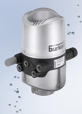
 New universal control head for hygienic process fittings
The Type 8681 control head is universally adaptable by means of adapters and can be combined with all commercially available valve types, such as flap valves, ball valves and single and double-seat valves, regardless of the manufacturer. Within the framework of a decentralised automation concept the control head, as a central unit for the hygienic process valves, performs all pneumatic actuation, feedback and diagnostic functions, as well as bus communication. Depending on the process valve, as many as three pneumatic driver chambers can be controlled separately.
The switching positions of the hygienic process valve are measured by the control head via an inductive analogue distance sensor for monitoring strokes of up to 85 mm and then transmitted to a master controller. After installation of the control head on the valve actuator the switching positions are automatically determined by a fast and reliable teach-in function, which eliminates the need for time-consuming manual configuration. If a fourth switching position is required, it can be read in by an externally mounted inductive proximity switch.

For optimal adaptation to the respective valve and process, the switching speed of each driver chamber can be set individually for both directions of movement by means of a restrictor function integrated in the pilot valve. In addition, a non-return valve prevents faulty switching of other driver chambers of the process valves due to back pressure. Independent of the power supply, each pilot valve can additionally be switched manually by means of a mechanical control. Thanks to a patented magnetically coded manual control, it is possible to switch the main actuator for maintenance purposes from outside even in the case of a completely enclosed device - ensuring full IP protection at all times.
 A highly visible three-colour optical status display with high-power LEDs, which is integrated in the control head, provides for an optimum overview at the field level. In addition to electrical feedback to the master controller, it also signals the current switching position of the process valve, facilitating diagnosis and maintenance within the system itself. Diagnostic functions such as required maintenance or errors are likewise signalled visually and can be read out in detail via a service interface. This communication can be wireless via a Bluetooth module or via the integrated USB interface.
Hygienic control valves are also suitable for decentralised automation
The use of one of the positioners or process controllers of the ELEMENT series allows the decentralised automation of control valves, in addition to the process valves. The ELEMENT process controllers are optimised for cleaning and use in the wet areas of hygienic processing plants; their outer geometry, materials, surface quality and sealing properties comply with EHEDG guidelines. The compact positioners are installed directly on the pneumatic actuator to save space and require no external hoses, thanks to the internal control air supply. Installation and commissioning are facilitated by the use of intelligent positioners with automatic adaptation and process controllers with automatic control circuit detection and parameter optimisation. Communication is achieved via Profibus DPV1, Device NET or the AS-Interface.
One decentralised system solution for all process levels
With the addition of the new Type 8681 control head to the ELEMENT series, Bürkert now offers a complete product portfolio for decentralised process automation in food and beverage production, breweries and the milk processing and pharmaceutical industries. The range of products extends from the process valve with an integrated pilot valve, as well as electrical and simple optical feedback all the way to the decentralised control of aseptic, hygienic control valves by means of a control head and process controller in complex production plants. decentralised automation can therefore be used in all processes for entire plants and installations, enabling users from these industries to combine the requirements for hygiene and safety with a high degree of automation and efficiency. Since the new control head can be used with virtually all available fittings regardless of the manufacturer, there are practically no limits to decentralised automation with uniform standards.
 To download the Burkert ELEMENT Conrtrol Valves
datasheet: click here
To download the Burkert ELEMENT Conrtrol Valves
datasheet: click here
The new flow transmitters at a glance
To receive more information on Burkert Element Valves please contact Forberg Scientfic customer service:
Phone: 855-288-5330Email: mechanicalsales@forberg.com
In the food and beverage industry, and also in the production of medicines and cosmetics, excellent hygiene in processes and around the plant plays a key role. This is ensured by stringent legislative regulations. Standards such as HACCP (Hazard Analysis and Critical Control Points) for food processing and GMP (Good Manufacturing Practise) for FDA-compliant processes in the pharmaceutical industry define extremely stringent requirements for cleanliness, safety and product quality. In addition, legislation requires that all processes must be constantly monitored and documented in these areas. In an increasingly competitive global environment, companies of this industry are at the same time forced to make their production processes as efficient and cost-effective as possible, in addition to optimising processes. As a consequence, there is an ever increasing demand for automation at all process and auxiliary circuit levels.
Pneumatically actuated process and control valves play a key role in the manufacture of foods and beverages, in milk processing and in the pharmaceutical and cosmetic industries. They are the core element of practically every production plant, where they perform numerous different tasks. However, the economical and hygienic aspects of these process fittings in a centrally controlled automation process are not unproblematic. Classical control systems using switch cabinets with valve terminals, I/O system and field bus interface involve considerable expense especially in complex facilities. With this technology, the fittings at the field level are connected to the control units in the switch cabinets through a large number of long control air lines and discrete feedback connections. Apart from planning and installation requirements for such solutions, they are not entirely optimal as regards hygiene. According to HACCP, every additional control air and feedback line within the production plant is a potential source of contamination and other risks and must therefore be monitored, serviced, cleaned and documented regularly, which is a costly undertaking.
In shop floor practice the control air lines can be quite long, which increases air consumption and has a negative effect on the switching times of the fittings. The situation is worsened even more by the high power requirement - e.g. for evacuation of air from chambers and hoses - which is undesirable in terms of energy efficiency. The fact that the pilot valve operating level is at a distance from the fitting makes it even more difficult to commission, maintain and extend the plant. This also applies to the monitoring of processes.
Intelligent valve systems make switch cabinets superfluous
A viable alternative to the use of central switch cabinets is the integration of the required automation functions in the fittings themselves. In this case, the process control system is only in charge of control and status monitoring. At field level, pneumatically operated valves are used. These can be equipped with all required automation components such as pilot valves with manual actuation, electrical feedback units and optical status indicators, field bus interfaces and even positioners and process controllers. By integrating an AS interface as a field bus interface, the entire range of advantages of this approach can be fully utilised. All that is required for power supply, feedback and communication is a two-wire line connecting the PLC with up to 62 valves. Each process valve is individually connected to the main compressed air supply line installed in the field, whereby these connections are kept as short as possible. This minimises the number and length of hose and wire connections.
For auxiliary circuits such as steam, compressed air or cleaning media, the valve specialist Bürkert offers fluid control systems with the intelligent valve systems of the ELEMENT series for creating decentralised automation solutions. The latest addition to this solution portfolio is the new control head Type 8681, which was designed especially for use with pneumatically actuated hygienic media valves. The features of a decentralised automation solution in hygienic production processes can be used to good advantage not only in the auxiliary circuits, but throughout the plant at all process levels. In the planning of new plants, the use of conventional switch cabinets can be eliminated consistently. Existing plants can be converted from central to decentralised automation step-by-step, using the existing media valves.

The Type 8681 control head is universally adaptable by means of adapters and can be combined with all commercially available valve types, such as flap valves, ball valves and single and double-seat valves, regardless of the manufacturer. Within the framework of a decentralised automation concept the control head, as a central unit for the hygienic process valves, performs all pneumatic actuation, feedback and diagnostic functions, as well as bus communication. Depending on the process valve, as many as three pneumatic driver chambers can be controlled separately.
The switching positions of the hygienic process valve are measured by the control head via an inductive analogue distance sensor for monitoring strokes of up to 85 mm and then transmitted to a master controller. After installation of the control head on the valve actuator the switching positions are automatically determined by a fast and reliable teach-in function, which eliminates the need for time-consuming manual configuration. If a fourth switching position is required, it can be read in by an externally mounted inductive proximity switch.

For optimal adaptation to the respective valve and process, the switching speed of each driver chamber can be set individually for both directions of movement by means of a restrictor function integrated in the pilot valve. In addition, a non-return valve prevents faulty switching of other driver chambers of the process valves due to back pressure. Independent of the power supply, each pilot valve can additionally be switched manually by means of a mechanical control. Thanks to a patented magnetically coded manual control, it is possible to switch the main actuator for maintenance purposes from outside even in the case of a completely enclosed device - ensuring full IP protection at all times.
 A highly visible three-colour optical status display with high-power LEDs, which is integrated in the control head, provides for an optimum overview at the field level. In addition to electrical feedback to the master controller, it also signals the current switching position of the process valve, facilitating diagnosis and maintenance within the system itself. Diagnostic functions such as required maintenance or errors are likewise signalled visually and can be read out in detail via a service interface. This communication can be wireless via a Bluetooth module or via the integrated USB interface.
Hygienic control valves are also suitable for decentralised automation
The use of one of the positioners or process controllers of the ELEMENT series allows the decentralised automation of control valves, in addition to the process valves. The ELEMENT process controllers are optimised for cleaning and use in the wet areas of hygienic processing plants; their outer geometry, materials, surface quality and sealing properties comply with EHEDG guidelines. The compact positioners are installed directly on the pneumatic actuator to save space and require no external hoses, thanks to the internal control air supply. Installation and commissioning are facilitated by the use of intelligent positioners with automatic adaptation and process controllers with automatic control circuit detection and parameter optimisation. Communication is achieved via Profibus DPV1, Device NET or the AS-Interface.
One decentralised system solution for all process levels
With the addition of the new Type 8681 control head to the ELEMENT series, Bürkert now offers a complete product portfolio for decentralised process automation in food and beverage production, breweries and the milk processing and pharmaceutical industries. The range of products extends from the process valve with an integrated pilot valve, as well as electrical and simple optical feedback all the way to the decentralised control of aseptic, hygienic control valves by means of a control head and process controller in complex production plants. decentralised automation can therefore be used in all processes for entire plants and installations, enabling users from these industries to combine the requirements for hygiene and safety with a high degree of automation and efficiency. Since the new control head can be used with virtually all available fittings regardless of the manufacturer, there are practically no limits to decentralised automation with uniform standards.

The new flow transmitters at a glance
- Beautiful stainless steel housing in standardized ELEMENT design
- Long durability and outstanding availability
- Removable, programmable display with backlight
- Programming via joystick
- New processors and software
- Future-proof system architecture
- Protection class IP 65/67
- Resistant to cleaning chemicals
- Up to two 700 mA transistor outputs
- Analog outputs 4-20mA
- UL approved
To receive more information on Burkert Element Valves please contact Forberg Scientfic customer service:
Phone: 855-288-5330Email: mechanicalsales@forberg.com
Monday, September 26, 2011
Select a Diaphragm Seal or Chemical Seal

When selecting a diaphragm seal assembly, the following details must be taken into consideration to ensure a safe and satisfactory operation. For specific technical assistance regarding temperature effects, volumetric compatibility, etc., contact the Forberg Scientific customer service department or send a completed diaphragm seal specification sheet to the factory for analysis.
- Process Composition
- Temperature
- Pressure Range
- Pressure Instrument
- Process Connection
- System Fill Fluid
- Mounting Positions
- Response Time
- Seal and Gauge Matches
1. Process composition
Since the diaphragm and lower housing of the diaphragm seal will be exposed to the process medium, it is critical to select materials for these components which will be compatible with this medium. Tables are available to assist in the selection of these materials (see Pressure Gauge Section); however, the customer is the ultimate source for specifying suitable materials. WIKA cannot guarantee suitability. For information, see numerous reference guides such as corrosion table reference books. If the pressure fluid is very thick, solidifies, or is full of solids, this should also be taken into consideration.
2. Temperature
Each diaphragm seal measurement system (diaphragm seal, pressure instrument, and cooling element or capillary, if applicable) is filled with an amount of fill fluid at an ambient temperature of about 70oF. This temperature is referred to as the system fill temperature. The fill fluid will expand or contract according to temperature changes. This in turn causes the pressure in the sensing element to rise or fall, thus adding zero shifting effects to the instrument output. To reduce this effect, the temperatures of the process and the environment should be specified when selecting a diaphragm seal system (see Diaphragm Seal Specification Sheet). Special advanced calibration techniques can be used to ensure the best possible accuracy. At temperatures above 300 F, a cooling element or capillary is suggested to protect the pressure instrument.
3. Pressure range
The displacement volume on the diaphragm seal required to "drive" each diaphragm seal measurement system (diaphragm seal, pressure instrument and capillary, if applicable) must be greater than the displacement volume needed to move the pressure sensing element. Normally, the lower the pressure range, the larger the diaphragm is required to "drive" the system. Conversely, for higher pressure ranges, smaller diaphragms are sufficient. Pressure transmitters also follow the general rule of the lower the pressure, the larger the diaphragm required.
4. Pressure instrument
As mentioned above (Item 3 - Pressure range), the diaphragm seal must supply sufficient displacement volume to enable the pressure instrument to reach full scale. As a general rule, smaller size gauges are better suited to low pressure applications since less displacement volume is required on the part of the diaphragm seal to drive the pressure instrument.
5. Process connection
The process connection is specified by the customer. Most process connections are threaded, flanged, or clamped; however, additional connections are available. Teflon® coating and lining is only available in flanged connections, since tapered NPT threads strip off the Teflon® during installation. However, solid Teflon® threaded connections are available with NPT threads.
6. System fill fluid
WIKA offers a wide range of system filling fluids allowing temperatures from -130 F to 752 F. Chemical compatibility of the system fill fluid with the process fluid must be carefully considered in the event of a leak. In food processing applications a nontoxic fluid should be selected. Special fill fluids are also available for oxidizing media such as oxygen and chlorine.
7. Mounting position
Mounting position is important for diaphragm seal systems which include a capillary. The level difference between the diaphragm seal and the pressure instrument causes a hydrostatic pressure to act on the sensing element: a. For gauges mounted above the level of the diaphragm seal, the pointer on the dial of the gauge will be lower than the zero point. b. For gauges mounted below the level of the diaphragm seal, the pointer on the dial of the gauge will be higher than the zero point. The diaphragm seal system can be calibrated to compensate for the effect caused by the hydrostatic pressure, if the level difference is known in advance.
8. Response time
Response time, i.e., the time it takes the pressure instrument to indicate 90% of the value of a sudden pressure variation, is especially important for instrument/diaphragm seal assemblies which include a capillary. Response time increases significantly in systems with long capillaries. In applications requiring long capillaries, response times can be reduced by using larger diameter capillary tubing and reducing the viscosity of the system fill fluid. Be advised that increasing the inner diameter of the capillary increases the temperature influence of the measuring system. Forberg Scientific can consult WIKA if detailed information is needed.
9. Seal and gauge matches
For low ranges, gauge preference is 2XX.54 or 2XX.34 for access to perform calibration adjustments. Gauges with crimp rings might not be usable due to potential recalibration. The table below shows the common matches between gauge and diaphragm seal types recommended by the WIKA.

If you would like additional information about WIKA Diaphragm Seals or other WIKA Products please contact Forberg Scientific, Inc.
Toll Free: 855-288-5330
Email: mechanicalsales@forberg.com
Friday, September 23, 2011
Diaphragm Seal & Chemical Seal Operating Principle
The drawing below illustrates the operating principle of a diaphragm seal assembly. A pressure measurementinstrument such as a conventional pressure gauge or electronic pressure transmitter is either mounted directly
to the diaphragm seal or attached to the seal by means of a capillary or cooling element.
A diaphragm within the diaphragm seal separates the gauge / transmitter from the process medium. Any part of the diaphragm seal (i.e., diaphragm, lower housing, gaskets) which will be exposed to the process medium is selected from materials resistant to pressure, temperature and possible chemical attack by the process medium.
The diaphragm seal is also filled with a transmitting fluid or system fill fluid. Any pressure applied by the process medium to the seal diaphragm is hydraulically transmitted to the pressure element of the gauge / switch / transmitter thus generating a pressure reading.
 If you would like additional information about
WIKA Diaphragm Seals
or other WIKA Products please
contact Forberg Scientific, Inc.
If you would like additional information about
WIKA Diaphragm Seals
or other WIKA Products please
contact Forberg Scientific, Inc.
Toll Free: 855-288-5330
Email: mechanicalsales@forberg.com
A diaphragm within the diaphragm seal separates the gauge / transmitter from the process medium. Any part of the diaphragm seal (i.e., diaphragm, lower housing, gaskets) which will be exposed to the process medium is selected from materials resistant to pressure, temperature and possible chemical attack by the process medium.
The diaphragm seal is also filled with a transmitting fluid or system fill fluid. Any pressure applied by the process medium to the seal diaphragm is hydraulically transmitted to the pressure element of the gauge / switch / transmitter thus generating a pressure reading.

Toll Free: 855-288-5330
Email: mechanicalsales@forberg.com
Wednesday, September 21, 2011
Diaphragm Seal or Chemical Seal Application
Diaphragm seals, also referred to as chemical seals, are used to isolate pressure gauges, switches, and transmitters from clogging and/or corrosive media. Standard diaphragm seal bodies and diaphragms are made of stainless steel; however, a variety of materials from carbon steel to Hastelloy® C-276 are available to meet the demands of most applications. WIKA diaphragm seals can operate in pressure applications from 10" H2O to 20,000 psi and media temperature between -130°F and 752°F.
EXAMPLES OF TYPICAL DIAPHRAGM SEAL APPLICATIONS
Toll Free: 855-288-5330
Email: mechanicalsales@forberg.com
EXAMPLES OF TYPICAL DIAPHRAGM SEAL APPLICATIONS
- The media is corrosive and may damage a sensitive element such as a Bourdon tube gauge, pressure switch or transmitter diaphragm.
- The temperature of the media may be too high for a standard gauge, switch or transmitter to operate properly.
- The media is highly viscous or tends to crystallize, or polymerize and may clog the pressure port of a gauge, switch or transmitter.
- The media is non-homogenous or contains suspended matter such as wood pulp which may clog the pressure port of a gauge, switch or transmitter.
- Remote reading is required. A diaphragm seal with a capillary line will allow remote installation of a pressure instrument.
- The sanitary cleanliness level is critical. A flush mounted or INLINE SEAL™ sanitary type diaphragm seal avoids dead space and cavities.
- The media is toxic or hazardous and may pollute the environment. A suitably designed diaphragm seal will provide additional protection.
- The application requires high overpressure protection. A diaphragm seal with a contoured diaphragm bed can be configured to provide overpressure protection and protection to the instrument.
- Meeting fugitive emission requirements
- Extending the service life of the pressure instrument
- Reducing the cost of installation
- Reducing or eliminating maintenance costs
Toll Free: 855-288-5330
Email: mechanicalsales@forberg.com
Friday, September 16, 2011
Commercial Roof and Gutter De-Icing Nelson Heat Trace

For commercial grade protection against ice dam formation on roofs, gutters and downspouts, look to our selection of cut-to-length, and pre-terminated heating cables. Nelson Heat Trace offer a wide range of choices in terms of voltage, power and construction, including mineral insulated cables that provide exceptional protection of the heating element. Solutions are available for corrosive and hazardous locations, along with all the accessories you need for a simple installation and the controls your customers need to operate the system easily and reliably.
 SMMC‐3 Control Panel. This three‐zone control panel allows each snow melting zone to be controlled independently or on a priority mode basis.

SLT‐C Universal Roof Clips. Are for use with all versions of Nelson’s SLT and CLT‐JT heating cables.
SLT‐RC Roof Clips. Are designed to fasten heating cable to most types of roof and gutter materials.
AT-50 Aluminum Foil Tape- may be used to secure the heater cable to the bottom of the gutter. Each roll of tape will accommodate 46M (150’) of gutter. Gutter must be clean for foil tape to adhere properly.

Nelson Type SLT heating cable is a parallel circuit, self-regulating electric heater. An irradiated crosslinked conductive polymer core is extruded over two multi-stranded, tin-plated, 16-gauge copper buswires. The conductive core material increases or decreases its heat output in response to temperature changes. Three jackets provide extra dielectric strength, moisture resistance, protection from impact or abrasion damage, and flame retardancy. The inner thermoplastic jacket is extruded over and bonded to the core material to prevent moisture penetration and wicking along the core. A waterproof thermoplastic elastomer outer jacket is then extruded over the inner jacket for dielectric protection and additional moisture resistance. A tinned copper braid is installed over the second jacket providing a continuous ground path. A flame retardant, UV stabilized polyolefin overjacket is then extruded over the braid.
If you would like more infomation about Nelson Heat Trace Products please contact Forberg Scientific, Inc.
Email customer service at processsales@forberg.com
Wednesday, August 31, 2011
A Pressure Transducer that Can Handle Just About Anything
Author: Wika
Have you ever had a pressure transducer succumb to high pressure, extreme heat, or cold? Have you had an application fail because a pressure transducer did not live up to its expectation? WIKA offers the R-1 as the latest generation of pressure transducers using thin-film and thick-film ceramic technologies for refrigeration and air conditioning systems.


Image Captions (Left to Right)
Long-term leak resistance of the R-1 pressure transducer is achieved through the hermetically sealed, welded thin-film sensor and process connection. Elimination of soft sealing materials removes the need for additional material compatibility testing and eliminates the chance of long term leaks developing due to seal deterioration.
Refrigeration & AC System Overview
 With the rapid increase in energy costs, energy efficient refrigeration and HVAC systems are essential. If operating your plant’s refrigeration systems involves a significant electricity expense, WIKA presure transducers for refrigeration and air conditioning can significantly reduce energy consumption when used in conjunction with a PLC based control system. Permanently installed pressure transducers make it simple to monitor the performance of your system and identify any problems that may occur.
The photograph at right is an example of a refrigeration application for which the WIKA R-1 pressure transducer would be used.
Description of a typical refrigeration cycle
Step 1: Beginning at the compressor, the refrigerant is compressed and leaves the compressor as a high temperature, high pressure gas.
Step 2: The hot refrigerant enters the condenser, which is usually fan forced air cooled; then the refrigerant leaves the condenser as a warm liquid and continues on to the thermal expansion valve.
Step 3: The expansion valve meters the proper amount of refrigerant into the evaporator.
Step 4: The sudden pressure drop after the expansion valve converts the high pressure warm liquid refrigerant into a low pressure, cold gas. The cold gas absorbs ambient heat from fan forced air passing through the evaporator. This ambient heat converts the refrigerant into a cool dry gas. From here the refrigerant reenters the compressor to be pressurized again and the cycle repeats.
The diagram below shows a typical refrigeration cycle. Image modified from Natural Resources Canada
 Pressure transducers are used on both the high pressure side and low pressure side of the compressor to control and optimize the cycle.
Low refrigerant charge in a refrigeration system is detected by monitoring the compressor’s discharge of pressure and temperature. This monitoring is accomplished with a WIKA pressure transducer located at or near the compressor outlet. Output signals from the pressure transducer are sent to a PLC. When a high discharge temperature with a low discharge pressure is detected, the PLC provides a low charge signal. The PLC can also receive input about additional operating characteristics of the refrigeration system to provide a more accurate low charge signal. The PLC is connected to a warning indicator and compressor so that the low charge signal activates the indicator and deactivates the compressor.
Refrigeration systems often suffer from hidden equipment faults and inefficient controls. Undetected problems in a refrigeration system can result in high energy costs and shorten the life of the equipment. By installing the proper monitoring equipment and adopting an efficient control strategy, costly problems can be prevented.
Potential problems
If you would like more information about the Wika R-1 Pressure Transducer or any other Wika Products please contact Forberg Scientific, Inc. Customer Service.
Toll Free: 855-288-5330
Email: mechanicalsales@forberg.com
Have you ever had a pressure transducer succumb to high pressure, extreme heat, or cold? Have you had an application fail because a pressure transducer did not live up to its expectation? WIKA offers the R-1 as the latest generation of pressure transducers using thin-film and thick-film ceramic technologies for refrigeration and air conditioning systems.
The R-1 pressure transducer is tested using strict protocols designed specifically for the refrigeration and HVAC industry. It meets or exceeds all test requirements including resistance to icing, heating, high pressure steam jets, internal condensation, submersion, and dust tightness.
Image Captions (Left to Right)
- Heat cycling: -15°F to +140°F to EN 60068-2-38
- Dust resistance: Ingress Protection IP6X according to EN 60529
- Submersion: 15PSI at 75°F for 30 minutes
- Freeze / thaw cycling: 40°F to 23°F for 240 hours
- High pressure steam washdown: Ingress Protection IPX9K to DIN 40050-9
- Condensation: +115°F ambient at 85% RH, media temp 15°F for 500 hours
Long-term leak resistance of the R-1 pressure transducer is achieved through the hermetically sealed, welded thin-film sensor and process connection. Elimination of soft sealing materials removes the need for additional material compatibility testing and eliminates the chance of long term leaks developing due to seal deterioration.
Refrigeration & AC System Overview
 With the rapid increase in energy costs, energy efficient refrigeration and HVAC systems are essential. If operating your plant’s refrigeration systems involves a significant electricity expense, WIKA presure transducers for refrigeration and air conditioning can significantly reduce energy consumption when used in conjunction with a PLC based control system. Permanently installed pressure transducers make it simple to monitor the performance of your system and identify any problems that may occur.
The photograph at right is an example of a refrigeration application for which the WIKA R-1 pressure transducer would be used.
Description of a typical refrigeration cycle
The diagram below shows a typical refrigeration cycle. Image modified from Natural Resources Canada
Pressure transducers are used on both the high pressure side and low pressure side of the compressor to control and optimize the cycle.Low refrigerant charge in a refrigeration system is detected by monitoring the compressor’s discharge of pressure and temperature. This monitoring is accomplished with a WIKA pressure transducer located at or near the compressor outlet. Output signals from the pressure transducer are sent to a PLC. When a high discharge temperature with a low discharge pressure is detected, the PLC provides a low charge signal. The PLC can also receive input about additional operating characteristics of the refrigeration system to provide a more accurate low charge signal. The PLC is connected to a warning indicator and compressor so that the low charge signal activates the indicator and deactivates the compressor.
Potential problems
- Suction line filters keep the refrigerant clean and protect the compressor from taking in debris. If one of the filters becomes clogged, the restricted flow will create a pressure drop in the system. This drop will reduce efficiency and lead to unnecessary costs.
- Hidden refrigerant leaks can eventually lead to a low refrigerant charge. Repairing leaks can bring about a remarkable performance boost. A low charge can cause efficiency losses and add to annual operating costs.
- In many refrigeration systems, head pressure stays at a fixed level to assure reliability over numerous temperature ranges. This also assists in maintaining sufficient refrigerant flow, freeze protection for the condenser and an adequate pressure difference across expansion valves.
If you would like more information about the Wika R-1 Pressure Transducer or any other Wika Products please contact Forberg Scientific, Inc. Customer Service.
Toll Free: 855-288-5330
Email: mechanicalsales@forberg.com
Monday, August 29, 2011
GPI Stainless Steel Turbine Liquid Flowmeter: What is it Good For?
Posted in Industrial Flow Meter Articles: Liquid Flow Meters by GPI on October 14, 2009

Edwin Starr’s lyrics in the classic, “War” tell the listener that war is good for “absolutely nothing!” When you talk about flowmeters with your friends, which I am sure all of us do, they probably think the same thing about the topic. Your friends think that flowmeters do absolutely nothing and they often wonder why someone would buy one of these objects.
If you are not in our industry, it is hard to explain why flowmeters make our universe whole or give us peace of mind. As we all know, flowmeters come in different shapes, sizes, materials, and flow ranges. Books could be written on each topic alone.
In this GPI informational article we will focus on how to use a stainless steel turbine flowmeter, how it is being used in various industries and other features of this popular meter. Plus, we will have an in-depth look at the GPI G2 Stainless Steel flowmeter.
AS GOOD AS IT GETS
A flowmeter that is made of stainless steel is one that does not rust, stain, or corrode easily when compared to other types of flowmeters that are made of different metals such as brass, aluminum etc. This is one of the main reasons why stainless steel turbine flowmeters are so popular. They are rugged meters that can take on some of the harshest chemicals without damage.
If you are looking for a meter that can sustain high pressure and harsh liquids you need to check out one of these stainless steel meters. The versatility of these meters can be seen in the ways it is used throughout different industries. There are some original equipment manufacturers (OEM) that use the meter for process control of chemicals in some of their applications. These manufacturers enjoy peace of mind by knowing that the chemicals being monitored have a good accuracy reading.
Manufacturers build these stainless steel turbine flowmeters differently. Some of these flowmeters are bigger, bulkier and the end user has to accommodate for space restrictions to make sure the application has ample room for the height and width of the meter. Other flowmeters are smaller and rugged in design so end users have flexibility when installing them in their applications.
If you are looking for a flowmeter that can handle some of the harshest conditions stainless steel is the way to go.
INDUSTRY USE
One of the popular uses of a stainless steel turbine flowmeter is to measure chemicals. These meters have excellent chemical compatibility allowing them to measure ammonia and boric acid. Stainless steel turbine flowmeters can take on some very obnoxious chemicals.
Bruce Patterson, Executive Products Manager at GPI, has over 20 years experience in the field of flowmeters. Patterson says,“ The versatile, stainless steel flowmeter performs great in most applications. These meters are currently used in environmental control, batching and blending of chemicals, temperature regulation, chillers and heaters, and in process control through out different markets.”
Cutting costs is always a great thing for business because it helps the bottom line. A flowmeter is a tool that can help companies save cash by cutting waste.
When asked about the potential impact these meters have on the bottom line, Patterson replied,
“It is a simple equation, the higher the accuracy you have when measuring fluids for your particular application the lower your risk of waste in measurement. Companies that are using this meter along with a batch controller are also in better shape when it comes to potential equipment break downs.”
FEATURES OF A STAINLESS STEEL FLOWMETER
Although there are many types of stainless steel turbine flowmeters in the industry let’s concentrate on the features of the GPI G2 Stainless Steel turbine flowmeter. The GPI G2 Stainless Steel turbine flowmeter has a local display with two totals, one is re-settable and one is cumulative. The meter is factory calibrated in gallons and litres.
The customer wants to calibrate it to their specific fluid the G2 Stainless Steel turbine flowmeter includes two field calibrations and flow rate. The accuracy rate depends on the meter size (see spec sheet here). The ease of repairing the internal parts is very popular with people using this meter. The G2 Stainless Steel flowmeters are plug-and-play ready. If the internals of the stainless steel flowmeters are damaged in use, they are easy to replace. All the user needs to do is take a retaining ring off and remove the damaged internals. Then replace the internals with a new kit. Many users really like this feature because it takes literally minutes to do. This means less down time to their operation.
This stainless steel turbine flowmeter has about 9,000 hours of battery life. Think about that for a second, which is the equivalent of about 9,000 NFL football games (minus the rest room breaks, beer & chip commercials, and time-outs called). The electronics in the display use Lithium batteries to provide it with the power necessary to run the display.
One of the best things about GPI G2 Stainless Steel turbine flowmeters is the class one division one rating. In simple English, this classification means that the flowmeter is explosion proof, intrinsically safe, and of the purged/pressurized type. Fancy lingo that lets users know there is no chance the flowmeter will cause a spark if it is used in a hazardous area. This is a great feature for someone wanting to use this meter but has to prove to management that the meter is safe to use in their hazardous application. In some industries they are required to prove that the piece of equipment that is going to be used has been approved by a number of regulatory organizations such as Factory Mutual (FM). Think of this as peace of mind approved.
 CONCLUSIONAs you can see from all this fancy data and the examples, stainless steel turbine flowmeters are good for users who want an accurate, rugged and dependable flowmeter. The only thing that these meters can’t do is start a war like the one on Edward’s song. However, the stainless steel turbine flowmeters can start a price war which wouldn’t be bad for the consumer.
Hopefully reading this gave you more insight on stainless steel turbine flowmeters in general along with useful information on the GPI G2 stainless steel turbine flowmeter. In the words of John Lennon, “Let us now give stainless steel flowmeters a chance”, okay he didn’t really say that but you get my drift or should I say flow?
If you would like more information about the GPI G2 Series Flowmeters or other GPI Flowmeters please contact Forberg Scientific, Inc Customer Service Representative.
Phone: 248-288-5990
Email: processsales@forberg.com
Tweet

Edwin Starr’s lyrics in the classic, “War” tell the listener that war is good for “absolutely nothing!” When you talk about flowmeters with your friends, which I am sure all of us do, they probably think the same thing about the topic. Your friends think that flowmeters do absolutely nothing and they often wonder why someone would buy one of these objects.
If you are not in our industry, it is hard to explain why flowmeters make our universe whole or give us peace of mind. As we all know, flowmeters come in different shapes, sizes, materials, and flow ranges. Books could be written on each topic alone.
In this GPI informational article we will focus on how to use a stainless steel turbine flowmeter, how it is being used in various industries and other features of this popular meter. Plus, we will have an in-depth look at the GPI G2 Stainless Steel flowmeter.
AS GOOD AS IT GETS
A flowmeter that is made of stainless steel is one that does not rust, stain, or corrode easily when compared to other types of flowmeters that are made of different metals such as brass, aluminum etc. This is one of the main reasons why stainless steel turbine flowmeters are so popular. They are rugged meters that can take on some of the harshest chemicals without damage.
If you are looking for a meter that can sustain high pressure and harsh liquids you need to check out one of these stainless steel meters. The versatility of these meters can be seen in the ways it is used throughout different industries. There are some original equipment manufacturers (OEM) that use the meter for process control of chemicals in some of their applications. These manufacturers enjoy peace of mind by knowing that the chemicals being monitored have a good accuracy reading.
Manufacturers build these stainless steel turbine flowmeters differently. Some of these flowmeters are bigger, bulkier and the end user has to accommodate for space restrictions to make sure the application has ample room for the height and width of the meter. Other flowmeters are smaller and rugged in design so end users have flexibility when installing them in their applications.
If you are looking for a flowmeter that can handle some of the harshest conditions stainless steel is the way to go.
INDUSTRY USE
One of the popular uses of a stainless steel turbine flowmeter is to measure chemicals. These meters have excellent chemical compatibility allowing them to measure ammonia and boric acid. Stainless steel turbine flowmeters can take on some very obnoxious chemicals.
Bruce Patterson, Executive Products Manager at GPI, has over 20 years experience in the field of flowmeters. Patterson says,“ The versatile, stainless steel flowmeter performs great in most applications. These meters are currently used in environmental control, batching and blending of chemicals, temperature regulation, chillers and heaters, and in process control through out different markets.”
Cutting costs is always a great thing for business because it helps the bottom line. A flowmeter is a tool that can help companies save cash by cutting waste.
When asked about the potential impact these meters have on the bottom line, Patterson replied,
“It is a simple equation, the higher the accuracy you have when measuring fluids for your particular application the lower your risk of waste in measurement. Companies that are using this meter along with a batch controller are also in better shape when it comes to potential equipment break downs.”
FEATURES OF A STAINLESS STEEL FLOWMETER
Although there are many types of stainless steel turbine flowmeters in the industry let’s concentrate on the features of the GPI G2 Stainless Steel turbine flowmeter. The GPI G2 Stainless Steel turbine flowmeter has a local display with two totals, one is re-settable and one is cumulative. The meter is factory calibrated in gallons and litres.
The customer wants to calibrate it to their specific fluid the G2 Stainless Steel turbine flowmeter includes two field calibrations and flow rate. The accuracy rate depends on the meter size (see spec sheet here). The ease of repairing the internal parts is very popular with people using this meter. The G2 Stainless Steel flowmeters are plug-and-play ready. If the internals of the stainless steel flowmeters are damaged in use, they are easy to replace. All the user needs to do is take a retaining ring off and remove the damaged internals. Then replace the internals with a new kit. Many users really like this feature because it takes literally minutes to do. This means less down time to their operation.
This stainless steel turbine flowmeter has about 9,000 hours of battery life. Think about that for a second, which is the equivalent of about 9,000 NFL football games (minus the rest room breaks, beer & chip commercials, and time-outs called). The electronics in the display use Lithium batteries to provide it with the power necessary to run the display.
One of the best things about GPI G2 Stainless Steel turbine flowmeters is the class one division one rating. In simple English, this classification means that the flowmeter is explosion proof, intrinsically safe, and of the purged/pressurized type. Fancy lingo that lets users know there is no chance the flowmeter will cause a spark if it is used in a hazardous area. This is a great feature for someone wanting to use this meter but has to prove to management that the meter is safe to use in their hazardous application. In some industries they are required to prove that the piece of equipment that is going to be used has been approved by a number of regulatory organizations such as Factory Mutual (FM). Think of this as peace of mind approved.

Hopefully reading this gave you more insight on stainless steel turbine flowmeters in general along with useful information on the GPI G2 stainless steel turbine flowmeter. In the words of John Lennon, “Let us now give stainless steel flowmeters a chance”, okay he didn’t really say that but you get my drift or should I say flow?
If you would like more information about the GPI G2 Series Flowmeters or other GPI Flowmeters please contact Forberg Scientific, Inc Customer Service Representative.
Phone: 248-288-5990
Email: processsales@forberg.com
Tweet
Subscribe to:
Posts (Atom)